
 This project has received funding from
the European Union's
This project has received funding from
the European Union's 
Equip Yourself for ZULF NMR!
In a previous blog post by James Eills, we have covered why ZULF NMR piques the interest of so many research groups and how it complements "conventional" high-field NMR. The only thing as interesting as the possibilities of ZULF NMR are all the solutions researchers have implemented over the last years to make ZULF NMR possible. Let's take a closer look into what makes measuring NMR at zero-to-ultralow field so different from high-field NMR.
The name of our experimental method already reveals the first important distinction to conventional NMR, where the sample is subjected to high (1-20 T) magnetic fields by being placed in middle of superconducting magnet. This polarizes the spins along the field axis, creating the net magnetism of the sample necessary for NMR detection. Below we will delve into ways of creating spin polarization in a ZULF NMR experiment.
In high-field NMR we observe the interaction of nuclear spins with magnetic fields (Larmor frequencies and chemical shift perturbations), and within the spectra we can often make out spin-spin couplings (J-couplings) which cause peaks to split into, often beautiful, sometimes complex, multiplet structures. These splittings can be small, and resolution of J-couplings at high field can be limited by the field homogeneity. Even a well-shimmed magnet can have gradients strong enough to broaden the peaks to such a degree that J-couplings are obscured! Additionally, certain samples (such as those with high magnetic susceptibility gradients, including metals) may destroy the field homogeneity. This isn’t a problem in ZULF NMR, since the field (and hence field gradients) are drastically scaled down, which allows us to resolve peaks with their natural line width, usually sub-Hz. To achieve the ultralow fields necessary for ZULF NMR, magnetic shielding is used to reduce the ambient magnetic field down to, typically, 1 nT or so. To further reduce the field, or vary the magnetic field’s spatial structure, it is common to use shim coils powered by low-noise current supplies. These days, this equipment is commercially available; see for example the Twinleaf MS-2 in Fig. 1.
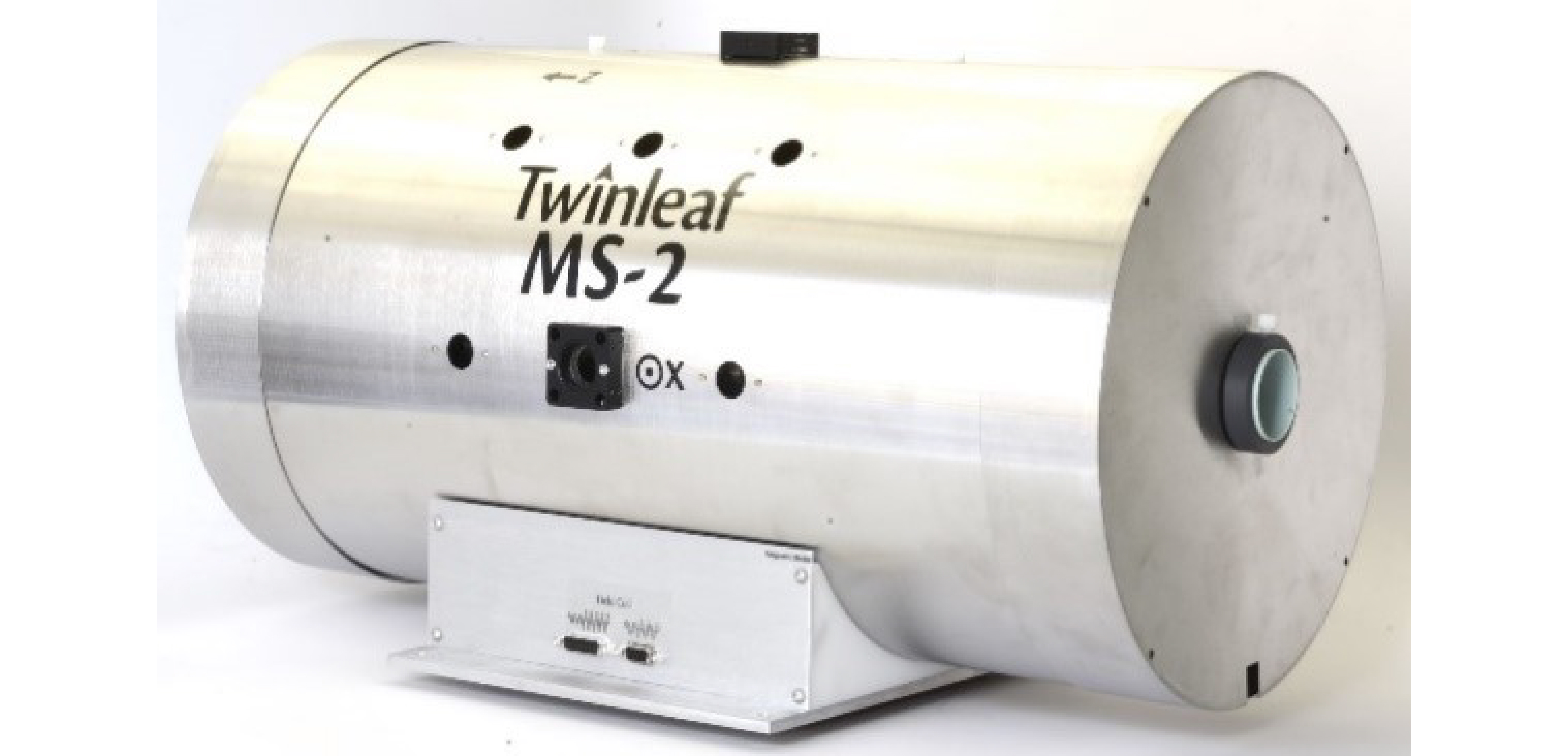
Figure 1: A magnetic shield consisting of multiple concentric chambers of mu-metal. Additionally, an inner layer of ferrite can be used to shield from Johnson noise in the mu metal. Image: MS-2 magnetic shield from Twinleaf LLC. Taken with permission from www.twinleaf.com.
Polarizing the spins
Before we jump into the spectroscopy, we're going to need something to detect..
NMR is an ensemble phenomenon, where before measuring signals one must initiate a magnetically ordered state. We call this process pre-polarization, and it is normally carried out by allowing the sample to thermalize in a magnetic field. The equilibrium polarization is proportional to field. Therefore, strong fields are favorable, but homogeneity is not a requirement. This leads us to the most common pre-polarization method used in ZULF NMR, field cycling.
Field cycling is based on mechanically moving the sample from a pre-polarization location, a powerful Halbach magnet (~2 T), to a detection region inside a magnetic shield. To maintain polarization, it is necessary to transfer sample inside of the guiding field, often generated by solenoid around the shuttling path. A limitation of this technique is the transfer time (around 0.5 s), but for the majority of compounds that we study with ZULF NMR, transfer times are much faster than the spin decoherence times. Therefore only a small fraction of the polarization is lost during the transport.
There is a variant of the prepolarization technique where instead of a magnet outside of the shield we would use a field generated by a coil inside of the shield, and keep the sample stationary[1]. This method is beneficial to samples with relaxation faster than the typical shuttling speed. In both cases, we would reach a degree of thermal polarization that allows for ZULF NMR detection.
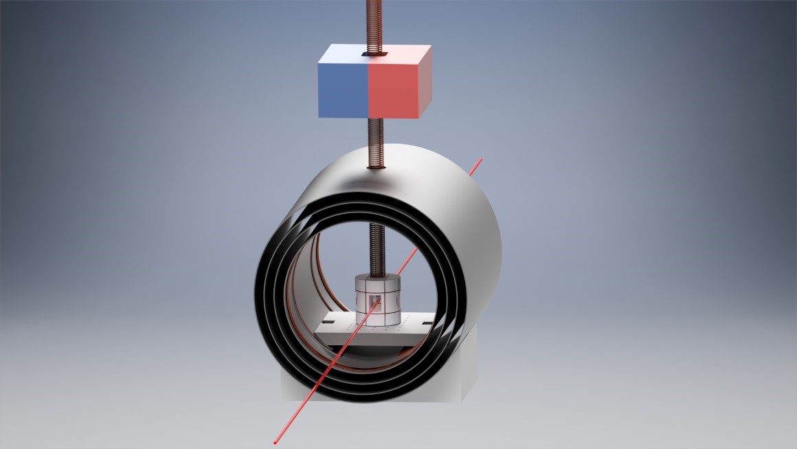
Figure 2: A simplified ZULF NMR setup, with the shield end-caps removed for illustration. Above the magnetic shield is a magnet for sample pre-polarization. A solenoid electromagnet provides a guiding magnetic field for samples passing through the layers of magnetic shielding. Beneath the solenoid is a coil former supporting Helmholtz coils to apply magnetic fields to the samples. The red line indicates a laser probing the nuclear spin polarization of the NMR sample, as part of detection by an optical magnetometer.
The higher the degree of pre-polarization, the higher the intensity the acquired signal will be, leading to improved signal to noise. But thermal polarization in a 2 T magnetic field gives only ~9 ppm polarization. At 20 T, or around 1 million dollars worth of magnet, we can only achieve 90 ppm. It is a significant engineering challenge to go far beyond these magnetic fields for sample pre-polarization. Luckily, we need not settle for mere polarization; we can hyperpolarize!
Hyperpolarization is a family of methods to reach near to the maximum nuclear spin polarization, therefore enhancing the sensitivity of the NMR technique by a factor up to several thousand. Hyperpolarization techniques include parahydrogen induced polarization (PHIP), signal amplification by reversible exchange (SABRE), dynamic nuclear polarization (DNP), spin-exchange optical pumping, and chemically induced dynamic nuclear polarization (CIDNP). These will be discussed in later articles in this blog. To summarize briefly, the general principle of NMR hyperpolarization is to transfer polarization from an external source to the nuclear spins within a sample.
Detecting the signal
Ok, great, we have some polarized spins. Now how do we detect them?
High field NMR signals are often at frequencies of 100-1000 MHz. In this regime, inductive coils are highly efficient for detection, since the signal amplitude increases in proportion with the Larmor frequency of the nuclear spins. Under ZULF conditions, the Larmor frequency is orders of magnitude lower (Hz to kHz). Therefore, the electric field induced by magnetic flux change in the detection coil can be millions of times smaller for the lower-frequency ZULF NMR signals; inductive detection is not the way forward.
There are more sensitive magnetometry techniques, such as optically pumped atomic magnetometers (OPMs), superconducting quantum interference devices (SQUIDs), and nitrogen-vacancy (NV) centers in diamond. In our labs we usually use spin-exchange relaxation free (SERF) OPMs, which were developed in the early 2000s[2] at Princeton University. How does an OPM compare to other detection options? Even high-temperature SQUIDS require a cryogenic refrigerator, are very temperature sensitive, and generate 1/f noise [3] which could prove to be limiting in the frequency range of interest in ZULF NMR (< 1 kHz). Magnetometers based on NV centers - on the other hand - aim to provide unparalleled spatial resolution and vector information about the field. However, despite their robustness, the achieved sensitivities at low frequencies of 15 pT/√Hz [4] are 2-3 orders of magnitude lower compared to capabilities of the average SERF magnetometer.
Nowadays, spectrometer construction can be greatly simplified by using a commercial OPM. They can save a lot of time and space, self-calibrate, and present a great option for groups not planning to dive into optics. However, building your own magnetometer allows for more advanced configurations for improved detection strategies such as gradiometry [5], and affords the possibility to position the OPM closer to the sample which improves sensitivity.
These days, a ZULF experiment can be put together with just a handful of commercially available components, most notably the magnetic shielding and magnetometer. In our lab it took mere days after the parts were delivered to have the experiment up and running.
Dr. Stephan Knecht, Technische Universität Darmstadt
OPMs use gaseous alkali metal atoms (e.g. rubidium) as a detection medium, that is placed in a transparent cell in the proximity of the NMR sample. The atoms are optically pumped – this is done by laser light that is close to the absorption line of the atomic medium. Such a beam transfers angular momentum between photons and atomic vapor atoms so that the atomic spins enter a highly polarized state. The polarized atoms are now highly sensitive to their external field; their spin will precess with a frequency proportional to field strength. This changed state of our polarized atoms can be measured by another laser, the 'probe' beam, and observing how the properties of the beam change. We usually observe the rotation or absorbtion of the probe beam light, which is sensitive to the field experienced by the alkali metal atoms.
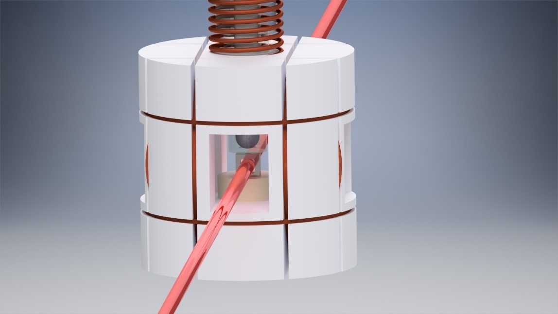
Figure 3: A body made from nonmagnetic material encloses the rubidium cell and holds pulse coils used for spin manipulation techniques. The atomic vapor cell is kept at around 180 ˚C. In this configuration, only one laser is passing the cell, and the intensity of the transmitted light is a function of the magnetic field.
It is often that magnetometers employed in ZULF NMR are working in the aforementioned spin-exchange relaxation free regime. Spin-exchange relaxation happens when optically polarized alkali atoms collide with each other due to thermal motion leading to loss of polarization. It is possible to reduce spin exchange relaxation, perhaps counterintuitively [6], by actually increasing the temperature of alkali vapor cell. The vapor cell contains a mixture of liquid- and gas-phase rubidium atoms. Going to higher temperature increases the atom density in the vapor phase, which reduces the mean free path of atoms in the cell to a degree where the collision rate is much faster than their precession speed, thus not giving them time to decohere. It is analogous to a full bus taking a sharp turn; with enough people there is no space to fall over.
There is much more that could be discussed with regards to instrumentation and many of those topics will receive their own blog post. We can conclude that possibilities emerging from the development of ZULF NMR techniques hold great potential, no small part of which is thanks to the cooperation of diverse research groups from all around the world. We believe that current results are a great motivation for many to join ZULF NMR! Possibilities are abundant and building your own ZULF spectrometer has never been easier [7].

Vladimir Kontul
I am a PhD student working at Jagiellonian University in Krakow, Poland, under the supervision of Prof. Szymon Pustelny, and one of the Early-Stage Researchers in the ZULF ITN. My focus is development of spectrometry instrumentation and software. Technologies in automatic optimisation, digital signal processing and pattern recognition are the main areas of my research and I am looking forward to bringing powerful tools to the ZULF NMR community.
Literature references:
- Tayler, M.C.; Ward-Williams, J.; Gladden, L.F.; Ultralow-field nuclear magnetic resonance of liquids confined in ferromagnetic and paramagnetic materials, Appl. Phys. Lett. 2019, 115, p.072409
- Budker, D.; Romalis, M.; Optical magnetometry, Nat. Phys. 2007, 3(4), pp.227-234
- Fagaly, R.L.; Superconducting quantum interference device instruments and applications, Rev. Sci. 2006, 77(10), p.101101
- Jensen, K.; Kehayias, P.; Budker, D.; Magnetometry with nitrogen-vacancy centers in diamond. In High sensitivity magnetometers, Springer, Cham. 2017, p. 553-576
- Jiang, M.; Picazo Frutos, R.; Wu, T.; Blanchard, J. W.; Peng, X.; Budker, D.; Magnetic Gradiometer for the Detection of Zero- to Ultralow-Field Nuclear Magnetic Resonance, Phys. Rev. Appl. 2019, 11, p.024005
- Allred, J.C.; Lyman, R.N.; Kornack, T.W.; Romalis, M.V.; High-sensitivity atomic magnetometer unaffected by spin-exchange relaxation, Phys. Rev. Lett. 2002, 89(13), p.130801
- Tayler, M.C.; Theis, T.; Sjolander, T.F.; Blanchard, J.W.; Kentner, A.; Pustelny, S.; Pines, A.; Budker, D.; Instrumentation for nuclear magnetic resonance in zero and ultralow magnetic field. Rev. Sci. 2017, 88(9), p.091101
Figure acknowledgements:
- Twinleaf LLC, available from: https://twinleaf.com/shield/MS-2/
- Piotr Put, Institute of Physics, Jagiellonian University, prof. Stanislawa Lojasiewicza 11, 30-348, Krakow, Poland